Testing IoT-02 board
Contingut
Programming firmware
Nice greetings to Nicko from Barcelona, Catalonia.
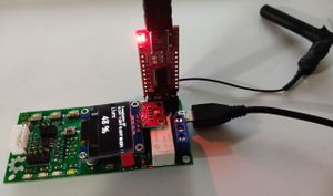
Connecting programmer
Red board: FT232RL FTDI USB to TTL Serial Adapter Module used as a programmer
It is very important to check jumper socket is at 3.3 volts position (by default it is at 5 volts)
Preparing uploading
Follow these steps on VirKO board:
- 1st: Connect 5V microusb power supply
- 2nd: Hold reset (red) button
- 3rd: While holding reset button, hold IO0 button (close to J1 black connector). At this step both buttons are being pressed.
- 4th: Release reset (red) button
- 5th: Release IO0 button
After these steps, board is ready to be programmed.
Programming from terminal
Software tool: esptool.py
Firmware binary files (this is testing firmware for VirKO board):
- 1/4) boot_app0.bin
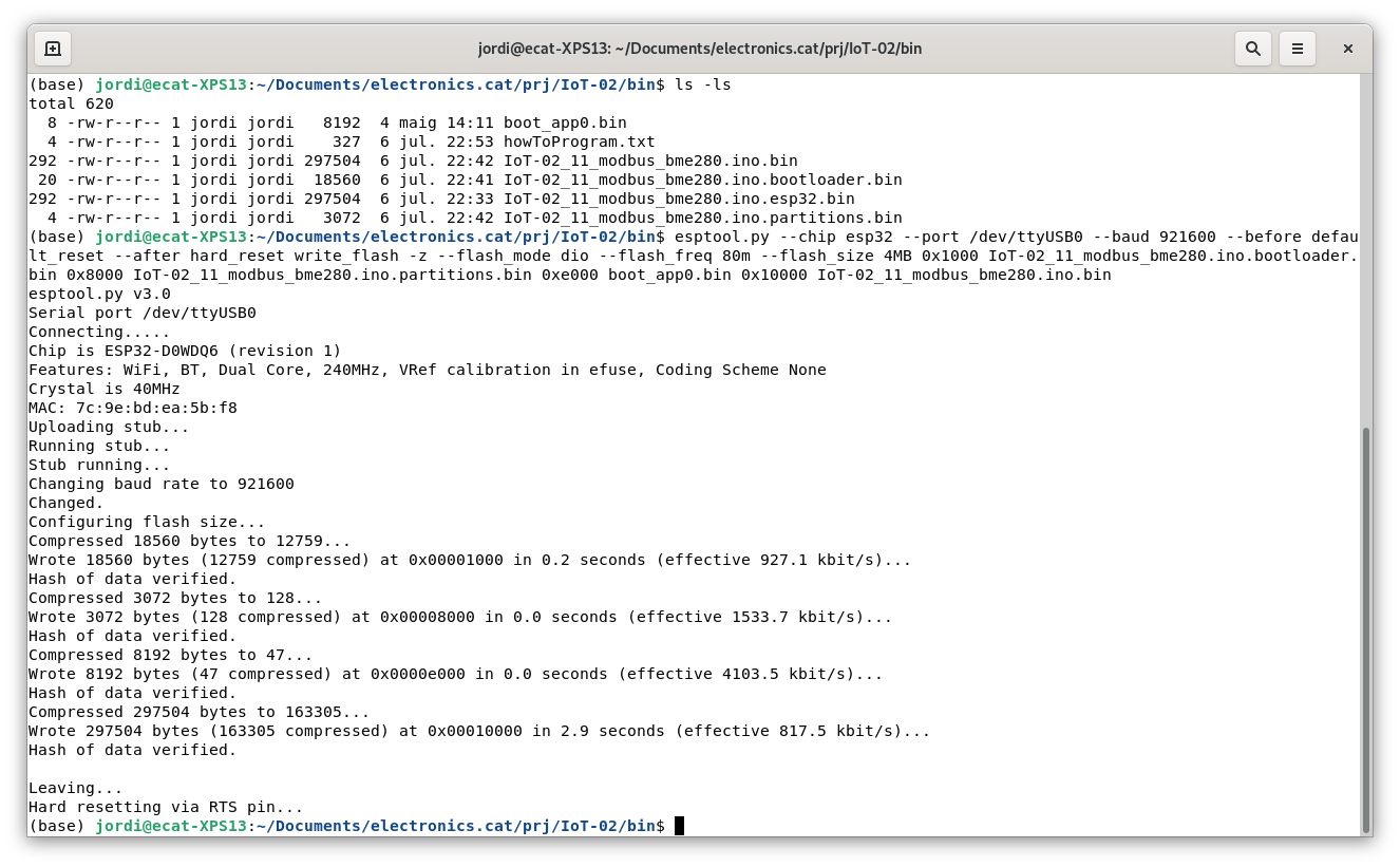
Terminal command:
esptool.py --chip esp32 --port /dev/ttyUSB0 --baud 921600 --before default_reset --after hard_reset write_flash -z --flash_mode dio --flash_freq 80m --flash_size 4MB 0x1000 IoT-02_11_modbus_bme280.ino.bootloader.bin 0x8000 IoT-02_11_modbus_bme280.ino.partitions.bin 0xe000 boot_app0.bin 0x10000 IoT-02_11_modbus_bme280.ino.bin
/dev/ttyUSB0 in Windows operating system is COMx port (being x programmer virtual port number. For instance: COM3)
Once programming is finished, reset button should be pressed again. Or remove red programming board and unplug power supply and plug again.
Programming from Windows tool
Prepare uploading with previously explained 5 steps, combining RST and IO0 buttons.
Windows program tool: Flash Download Tools (Explanation about Flash Download Tools use)
Once programming is finished, reset button should be pressed again. Or remove red programming board and unplug power supply and plug again.

