Testing VirKO board
De Wiki d'en Jordi Binefa
La revisió el 22:40, 8 set 2021 per Jordi (discussió | contribucions)
Contingut
Programming firmware
Nice greetings to Nicko from Barcelona, Catalonia.
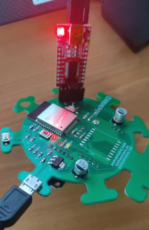
Connecting programmer
Red board: FT232RL FTDI USB to TTL Serial Adapter Module used as a programmer
It is very important to check jumper socket is at 3.3 volts position (by default it is at 5 volts)
Preparing uploading
Follow these steps on VirKO board:
- 1st: Connect 5V microusb power supply
- 2nd: Hold reset (red) button
- 3rd: While holding reset button, hold IO0 button (close to J1 black connector). At this step boths buttons are being pressed.
- 4th: Release reset (red) button
- 5th: Release IO0 button
After these steps, board is ready to be programmed.
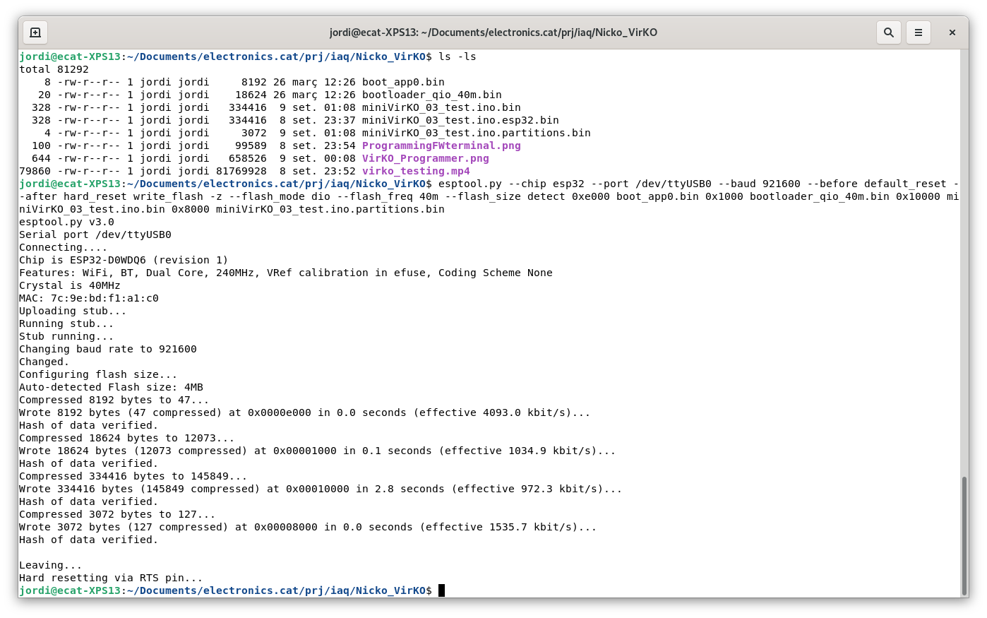
Programming from terminal
Software tool: esptool.py
Firmware binary: miniVirKO_03_test.ino.esp32.bin
Terminal command:
esptool.py --port /dev/ttyUSB0 write_flash -fm dio 0x00000 miniVirKO_03_test.ino.esp32.bin
/dev/ttyUSB0 in Windows operating system is COMx port (being x programmer port number. For instance: COM3)
Programming from Windows tool
Flash Download Tools (Explanation about Flash Download Tools use)

