Diferència entre revisions de la pàgina «Testing VirKO board»
De Wiki d'en Jordi Binefa
m (→Connecting programmer) |
m (→Programming firmware) |
||
| Línia 2: | Línia 2: | ||
== Connecting programmer == | == Connecting programmer == | ||
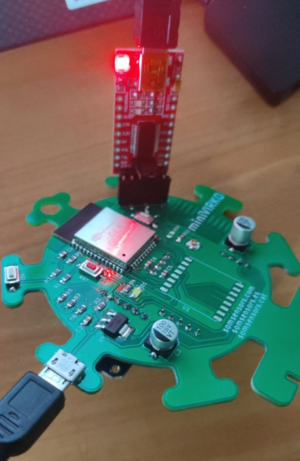
Red board: [https://www.aliexpress.com/item/4000566777448.html FT232RL FTDI USB to TTL Serial Adapter Module used as a programmer] | Red board: [https://www.aliexpress.com/item/4000566777448.html FT232RL FTDI USB to TTL Serial Adapter Module used as a programmer] | ||
| + | |||
| + | '''It is very important to check jumper socket is at 3.3 volts position (by default it is at 5 volts)''' | ||
[[Image:VirKO_Programmer.png|center|thumb|Programming firmware from terminal]] | [[Image:VirKO_Programmer.png|center|thumb|Programming firmware from terminal]] | ||
| + | |||
| + | == Preparing uploading == | ||
| + | 1st: Connect 5V microusb power supply | ||
| + | |||
| + | 2nd: Hold reset (red) button | ||
| + | |||
| + | 3rd: While holding reset button, hold IO0 button (close to J1 black connector). At this step boths buttons are being pressed. | ||
| + | |||
| + | 4th: Release reset (red) button | ||
| + | |||
| + | 5th: Release IO0 button | ||
| + | |||
| + | After these steps, board is ready to be programmed. | ||
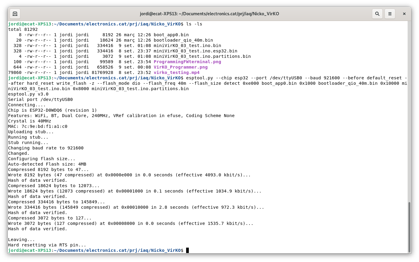
== Programming from terminal == | == Programming from terminal == | ||
Revisió del 22:23, 8 set 2021
Contingut
Programming firmware
Connecting programmer
Red board: FT232RL FTDI USB to TTL Serial Adapter Module used as a programmer
It is very important to check jumper socket is at 3.3 volts position (by default it is at 5 volts)
Preparing uploading
1st: Connect 5V microusb power supply
2nd: Hold reset (red) button
3rd: While holding reset button, hold IO0 button (close to J1 black connector). At this step boths buttons are being pressed.
4th: Release reset (red) button
5th: Release IO0 button
After these steps, board is ready to be programmed.

